How to Route Clean Orthogonal Manhattan Wires in Schema Editor
Step-by-step guide: configure grid snapping, draw orthogonal 90° wires between components, route around obstacles with auto-avoidance, and toggle 45° chamfers.
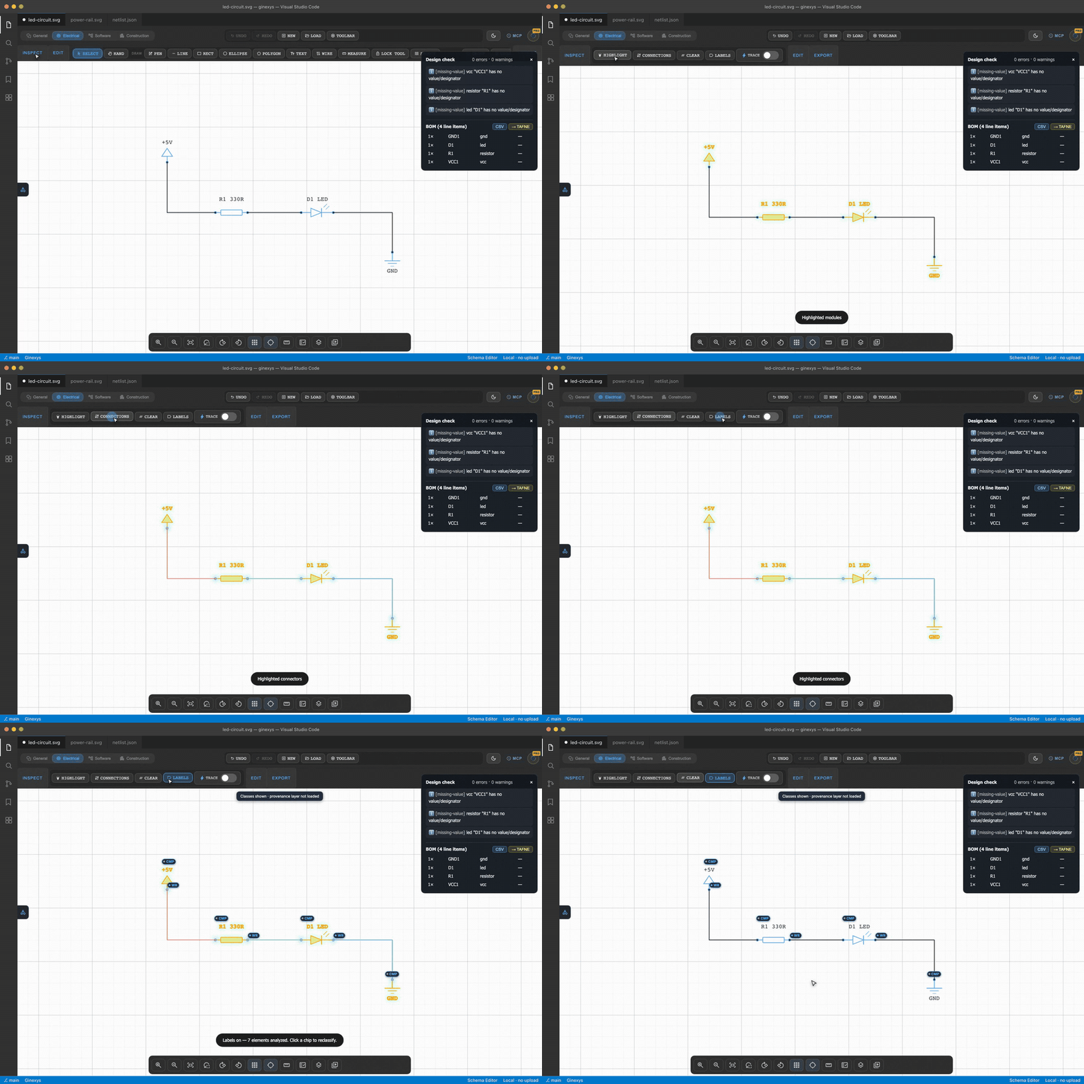
TLDR
Select the Wire Tool in Schema Editor (or press W), click any component pin, and guide your cursor to the destination. The Manhattan routing engine automatically draws right-angle orthogonal segments that snap to the grid and steer around intervening components. Use the toolbar slider to toggle between sharp 90° corners and clean 45° chamfers.
Before you start
You need Schema Editor open in any schematic or diagramming mode.
The grid snapping and Manhattan pathfinding engine runs client-side on an interactive SVG canvas, delivering instant 60 FPS snapping even on dense schematics with hundreds of components.
Step 1 — Configure grid size and snapping rules
In the bottom-right status bar, click the Grid Settings menu:
- Grid Size: Choose between
10px,20px, or40pxgrid pitches. A20pxpitch works best for standard electrical schematics. - Snap to Grid: Ensure the magnet toggle is active (or press
Gto toggle snapping on and off). - Pin Snap Radius: Controls the magnetic pull distance when your cursor nears a terminal pin (default:
8px).
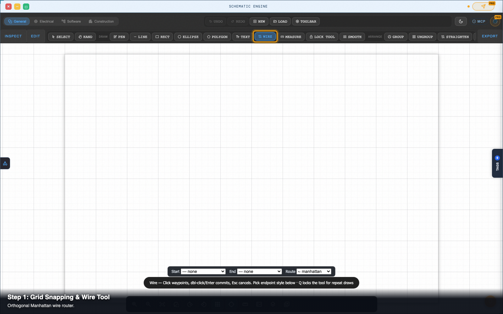
Step 2 — Draw orthogonal 90-degree wires between pins
Press W (or click the Wire Tool icon in the left toolbar).
- Hover over the starting component terminal pin. A green connection ring appears.
- Click to anchor the starting wire endpoint.
- Move your cursor toward the target component. The router renders orthogonal horizontal and vertical segments that follow the grid lines.
- Click the destination pin to commit the wire.
Step 3 — Route around obstacles with auto-avoidance
When an existing component or chip sits directly between two pins:
- Move your cursor past the obstacle.
- The pathfinder evaluates obstacle bounding boxes in real time, automatically routing the wire above, below, or around the blocking element without crossing over component bodies.
- To force an intermediate corner, click once in empty canvas space to drop a manual waypoint, then continue routing.
Step 4 — Adjust wire elbows and add 45-degree chamfers
After a wire is placed, you can adjust its routing path:
- Drag Segments: Click and drag any horizontal or vertical wire segment to shift it up, down, left, or right while preserving 90° junctions.
- Add 45° Chamfers: In the top toolbar, drag the Chamfer Slider (or set it to
6px). The sharp 90° corners smoothly convert into 45° diagonal joints, providing a professional CAD look.
Step 5 — Reposition components without breaking connectivity
Select the Move / Pointer Tool (V or Escape).
Click and drag any placed component (such as an IC or resistor) to a new canvas location:
- Attached wires stretch and reroute orthogonally in real time.
- Connected pins stay firmly attached with zero disconnected dangling wires.
- Multi-wire junctions update their coordinate nodes automatically.
Pro tip: hold Shift for temporary free-angle routing
By default, the wire tool strictly locks to orthogonal 90° and 45° Manhattan angles.
If you need to draw a non-standard diagnostic tap or free-angle indicator arrow, hold Shift while routing to temporarily unlock free 360° vector angle drawing.
Next steps
Schema Editor — Draw and edit wiring diagrams, schematics, ERDs, and state machines as real SVG.